LED Array information
The MSE-Embedded platform contains a LED-Array of 4 colums times 8 rows (so a total of 32 LEDs) as indicated in the below figure.
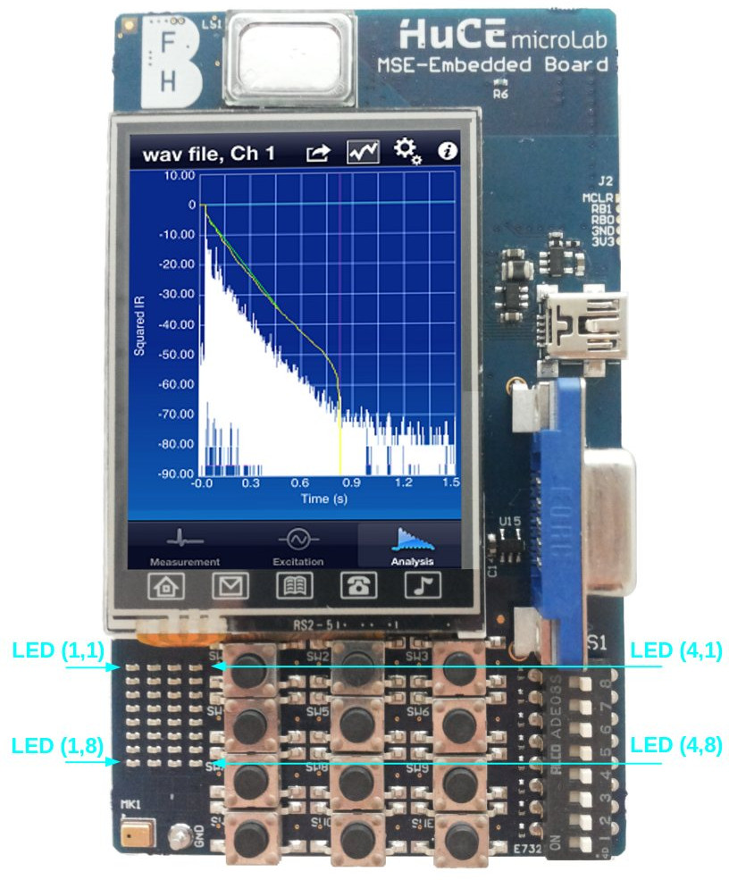
Each of these LED's is connected to an individual FPGA-pin. The LED lights up if a logic 1 is written to the pin and is off in case of a logic 0 (the LED's are active high).
The below table indicates at which FPGA-pin each of the LED's of the LED-array is connected. And here you find an example tcl script that can be used for pin-assignment in Quartus.
| LED | PIN | LED | PIN | LED | PIN | LED | PIN |
|---|---|---|---|---|---|---|---|
| (1,1) | PIN_M5 | (2,1) | PIN_M7 | (3,1) | PIN_J5 | (4,1) | PIN_J7 |
| (1,2) | PIN_N6 | (2,2) | PIN_N8 | (3,2) | PIN_B2 | (4,2) | PIN_K8 |
| (1,3) | PIN_N5 | (2,3) | PIN_N7 | (3,3) | PIN_B1 | (4,3) | PIN_K7 |
| (1,4) | PIN_P6 | (2,4) | PIN_P7 | (3,4) | PIN_C2 | (4,4) | PIN_L8 |
| (1,5) | PIN_P5 | (2,5) | PIN_R7 | (3,5) | PIN_C1 | (4,5) | PIN_G5 |
| (1,6) | PIN_R6 | (2,6) | PIN_T7 | (3,6) | PIN_D2 | (4,6) | PIN_H6 |
| (1,7) | PIN_R5 | (2,7) | PIN_L6 | (3,7) | PIN_L7 | (4,7) | PIN_H5 |
| (1,8) | PIN_T5 | (2,8) | PIN_M6 | (3,8) | PIN_M8 | (4,8) | PIN_J6 |